FLANK — 01
Multi Axis Flank Contouring 1
- Select the Drive Surface, Part Surface, Guide, Start Point, and Stop Point.
- Select a Ø10 mm Flat End Mill as the cutting tool.
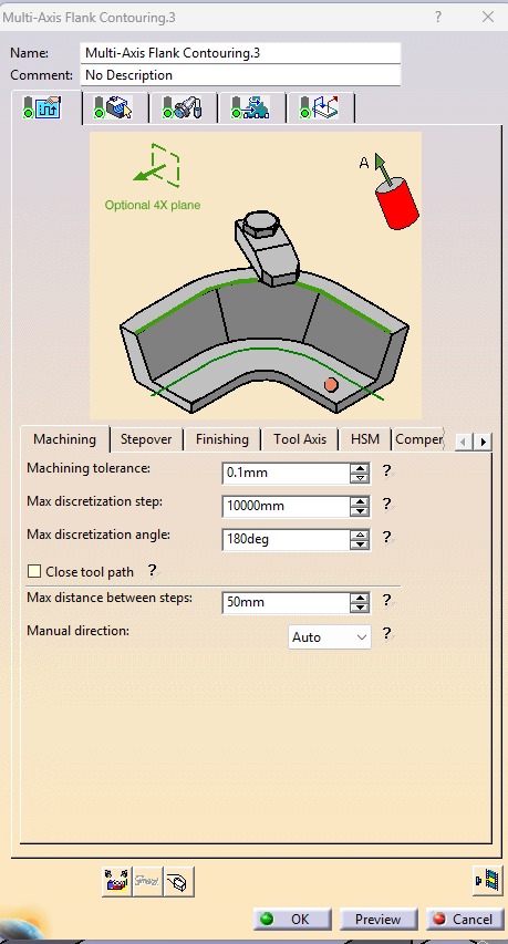
- Set the Machining Tolerance to 0.1 mm.
- Set the Tool Path Style to One Way.
- Set the Distance Between Paths to 0.8 mm.
- Set the Number of Paths to 2.
- Set the Guidance Mode to Tanto Fan.
- Activate the Approach and Retract options.
- Set the Approach to Axial Motion Up to a Plane, with Motion to a Point enabled.
- Enable Tool Axis Motion and set the Tool Axis Definition to K = 1.
- Compute the toolpath and verify that it is generated correctly.
- Run the machining simulation to check the tool movement, verify there are no collisions or gouges, and ensure the surface is machined accurately before generating the NC code.
.jpeg)
.jpeg)
.jpeg)
.jpeg)