FLANK — 03
Multi Axis Flank Contouring 3
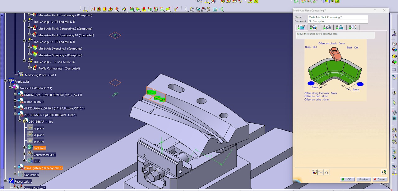
- Select the Part Surface, Drive Surface, Guide, Start Point, and Stop Point.
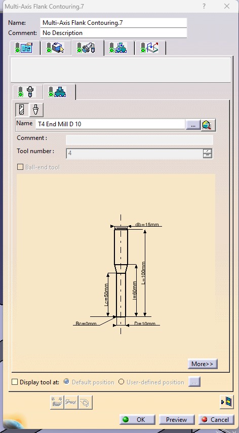
- Select a Ø10 mm Flat End Mill as the cutting tool.
- Set the Tool Path Style to One Way.
- Set the Distance Between Paths to 5 mm.
- Set the Number of Paths to 1.
- Set the Guidance Mode to Mixed Combin.
- Activate the Approach and Retract options.
- Configure the Approach with Axial Motion Up to a Plane, Motion to a Point, Tool Axis Motion, and Circular Motion. Set the Circular Motion value to 2 mm.
- Activate Return Between Level Retract and Return Between Level Approach.
- Set both Return Between Level Retract and Return Between Level Approach to Circular Motion = 2 mm and Axial Motion Up to a Plane.
- Compute the toolpath to generate the machining operation.
- Run the machining simulation to verify the toolpath, check for collisions or gouges, and ensure the surface is machined correctly before generating the NC code.
.jpeg)
.jpeg)
.jpeg)
.jpeg)
.jpeg)