FLANK — 02
Multi Axis Flank Contouring 2
- Select the Part Surface, Drive Surface, Guide, Start Point, and Stop Point.
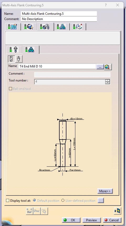
- Select a Ø10 mm Flat End Mill as the cutting tool.
- Set the Tool Path Style to One Way.
- Set the Distance Between Paths to 5 mm.
- Set the Number of Paths to 1.
- Set the Guidance Mode to Mixed Combin.
- Activate the Approach, Retract, and Return options.
- For Approach, set Axial Motion Up to a Plane, Motion to a Point, Tool Axis Motion, and set the Tolerance to 50 mm.
- For Return in a Level, configure Retract and Approach with Axial Motion Up to a Plane and Motion to a Point.
- Compute the toolpath and run the first machining simulation to verify the tool movement, check for collisions, and ensure the machining operation is correct.
- Copy the completed machining operation and paste it to create a second operation.
- Re-select the Part Surface, Drive Surface, Guide, Start Point, and Stop Point for the copied operation.
- Recompute the toolpath and run the second machining simulation to confirm that the copied operation produces the required machining result without errors.
.jpeg)
.jpeg)
.jpeg)
.jpeg)
.jpeg)
.jpeg)
.jpeg)